Perspective
Perspective is a method for producing realistic pictures. It is a mathematical system that indicates how a real-world scene would project to a vantage point. If a picture is to be produced, a picture surface is placed between the real-world scene and the vantage point. Each point of interest in the real-world scene is joined to the vantage point by a straight line. A depicting point is placed on the picture surface where the line intersects it. Perspective pictures look realistic because they recreate the pattern of light of the real-world scene.
When viewing a picture, the task of vision could be called “inverse projection”, using the light from the picture to determine the depicted real-world scene. The observer should entertain directions traveling from the vantage point, to points on the picture surface, and beyond. Alas, the inverse-projection problem is an induction problem, and so there are infinite solutions. Given a puzzle with an infinite number of solutions, how is one solution picked?
Vision does not follow perspective exactly. It has its own solution to the inverse projection problem. The solution is derived from a combination of “visual angle ratio” and “angle from normal”. The “visual angle ratio” is the ratio of the visual angle of the depth of an object divided by the visual angle of the width of an object. The “angle from normal” is the angle between the line joining the observer to the central vanishing point, and the line to a point on the object. That the two factors, visual angle ratio and angle from normal, are important carriers of information can be inferred from first principles.
Empirical studies reveals that the solution that vision uses to find perceived relative depth (the perceived depth/perceived width of an object) is a linear combination of the two factors, with visual angle ratio weighted an order of magnitude greater than angle from normal, that is:
Perceived Relative Depth = α(Visual Angle Ratio) + β(Angle from Normal) + c, where α, β, and c are all real numbers, with α approximately 10 times β, and angles measured in radians. This solution to the inverse projection problem is an approximation to correct perspective.
An observer looking at the painting “The School of Athens” by Raphael (Figure 1) gets an impression similar to that from observing a real scene in Athens. In other words, the painting looks realistic. This realism is provided by perspective. Here, we outline the principles of perspective and show how vision uses perspective pictures.

Figure 1. Raphael’s (1483-1520) The School of Athens (1510-11), Stanza della Segnatura (Vatican).
Perspective is a mathematical system that indicates how a real-world scene would project to a vantage point (see Figure 2). To depict a scene in perspective, a vantage point is chosen and a picture surface is placed between it and the scene. Each point in the scene (e.g., the top leaf of a tree, the tip of a blade of grass, the border of a lake, etc.) is depicted by a point on the picture surface as determined by perspective projection. Specifically, each point of interest in the scene is joined to the vantage point by a straight line. A depicting point is placed on the picture surface where the line intersects it (see Figure 2).
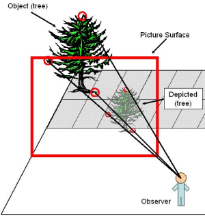
Figure 2. A perspective projection of an object (tree) onto a picture surface. Points in the scene (indicated by the large red circles) are depicted by a point on the picture surface (indicated by the smaller red circles) as determined by perspective projection.
Perspective pictures look realistic because they recreate the pattern of light of the real-world scene. That is, an observer looking at a real-word scene receives a certain pattern of light (see Figure 3A), which gives the observer a certain percept of the scene. Perspective geometry allows a picture to recreate that pattern of light (see Figure 3B). Hence, looking at the perspective picture, the observer once again can have the same percept of the scene, though now the pattern of light is created by a picture, rather than the real-world scene (see Figure 3C). Realism is achieved by recreating patterns of light typically found in real-world scenes.
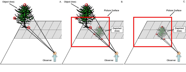
Figure 3. (A) The observer looking at the real-word tree receives a certain pattern of light, indicated by the three arrows. From this pattern the observer perceives the tree. (B) Perspective geometry allows a perspective picture to recreate that same pattern of light. (C) Looking at the perspective picture, the observer once again can have the same perception of the tree. Now, however, the pattern of light, indicated by the three arrows, is created by a picture of the tree, rather than the real-world tree.
Since a scene point is projected onto a picture surface, perspective is a projective geometry, used to depict 3-D scenes on 2-D surfaces. Its invention during the Renaissance is credited to Filippo Brunelleschi (1377-1446), sculptor, architect, and artisan-engineer. Reportedly, Brunelleschi invented perspective while drawing an octagonal building, the Baptistry in Florence, with two of the sides receding at 45º to the picture surface (Tyler and Kubovy, 2004; Veltman, 1998). These sides would be drawn with converging lines. Brunelleschi is thought to have devised a geometrical proof showing how much convergence to use for an artist looking at the scene while standing a certain distance from the picture surface (see Technical Note #1). The first perspective painting that Brunelleschi showed to others was a picture of the church of Saint Giovanni of Florence. This is widely regarded as the first accurate perspective picture. Brunelleschi left no record of his perspective experiments, but probably passed his proof verbally to other artists. Fortunately, in 1435, Leon Battista Alberti wrote a treatise, “Della pittura” (“On painting”), which was dedicated to Brunelleschi and contained a section on perspective.
Since its discovery in the Renaissance, perspective has been the standard method for making realistic pictures.
The Inverse Projection Problem
The theory of geometrical perspective, producing a picture of a 3-D scene on a 2D picture surface, is simple. Indeed, the mathematics involved is covered in most high-schools. Does vision follow the laws precisely or only approximately?
When viewing a picture, the task of vision could be called “inverse projection” (Niall, 1992; Niall and Macnamara, 1989, 1990; Norman, Todd, Perotti, and Tittle, 1996; Wagner, 1985), using the light from the picture to determine the depicted 3-D scene. Looking at a perspective picture, from the vantage point used to create the picture, means being in the same position in front of the picture that the artist was when drawing it. To determine the real world scene depicted by the picture, “invert the projection”. That is, the observer should entertain directions traveling from the vantage point, to points on the picture surface, and beyond (see Figure 4). On the far side of the picture surface, at the end of each direction line is where the relevant real world 3-D point would be. Alas, there is an infinite distance on the far side of the picture surface. Depicting points establish the directions of the scene’s points, but not their distance (see Figure 4). Where should the direction lines stop? Additional constraints are needed to settle on a particular inverse projection to a particular distance.
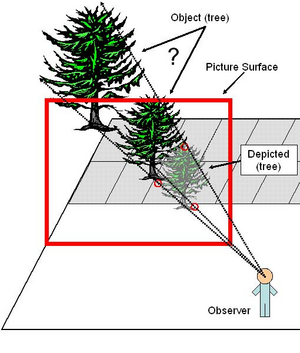
Figure 4. The “inverse projection” problem. Given the perspective picture, how does the visual system decide which tree is the true real world scene?
The inverse projection problem is an induction problem. That is, given a puzzle with an infinite number of solutions, how is one solution picked? To establish how perception comes to favor one solution rather than another, empirical studies – experiments on perception – are needed. The kinds of patterns that typify the real world must be shown surrounding a given depicting point in a picture, and observers’ reactions to the pattern tested. The most significant pattern is the one characterizing a ground plane, the matrix on which objects stand, the continuous surface that connects bases of objects.
Empirical study reveals that there are distortions in perception of perspective pictures. Piero della Francesca reported that Renaissance observers complained of a lack of fidelity in perspective pictures (della Francesca, 1480/1981). He noted that many observers, “… were in doubt whether perspective is a true science, judging it falsely from ignorance.” (p. 261). He went on to mention that the problem was that, in some pictures of tiles, for instance, “…those foreshortened appear larger than those not foreshortened.”
(p. 261). Perspective pictures have a single correct vantage point. However, pictures are often observed from many different vantage points. Many pictures that are drawn in perfect perspective appear distorted under two conditions, first when viewed from the incorrect vantage point and, second, when the picture is a wide-screen panorama.
Figure 5 depicts square tiles on a ground plane in perfect perspective. Many of the tiles in the middle regions often appear to be square tiles. This is the common phenomenon encountered when looking at perspective pictures, and has been called perspective robustness. But, as della Francesca (1480/1981) noted, many tiles often do not look square. For example, many tiles near the bottom corners of the picture typically look too long to be square. This phenomenon is referred to as perspective distortion. In this case the tiles look “forelengthened” (the opposite of foreshortened). The forelengthening distortion is often readily noticeable in the periphery of pictures (e.g., panoramic pictures taken with wide angle lenses), and is referred to as marginal distortion. There are also, however, central distortions (Juricevic and Kennedy, 2005a; 2005b, 2005c). For example, many of the tiles in Figure 5 that are off in the distance, close to the horizon, appear too compressed (too foreshortened) to be square tiles to many observers.
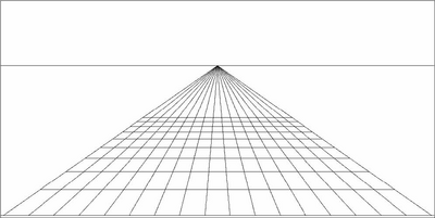
Figure 5. A perspective picture of a series of square tiles on a ground plane. As can be seen, the “inverse projection” is only successful sometimes. Evidently, perception does not follow perspective exactly. It has its own solution to the inverse projection problem.
In theory, the solution is derived from a combination of “visual angle ratio” and “angle from normal” (see Figure 6). The “visual angle ratio” is the ratio of the visual angle of the depth of an object divided by the visual angle of the width of an object. The “angle from normal” is the angle between the line joining the observer to the central vanishing point, and the line to a point on the object (see Figure 6). This solution to the inverse projection problem, utilizing the visual angle ratio and angle from normal, is known as the ART (Angles and Ratios Together) theory (Juricevic and Kennedy, 2005a; 2005b, 2005c).
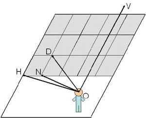
Figure 6. Consider the Observer (O) standing in front of a ground plane covered with tiles. The visual angle ratio of a tile is defined as: ∟DON / ∟HON. The angle from the normal of a tile is defined as the ∟VON.
Why should these two factors be helpful in solving the inverse projection problem? Consider the standard, clear case of perceiving the scene in Figure 5, that is, square tiles lying on the ground. Let us look at the information provided by the visual angle ratios and angles from the normal of these tiles. Consider visual angle ratio first.
Every object has a visual angle ratio since every object has a width and a depth. The range of possible visual angle ratios is from 0 to infinity, it can be shown (see Technical Note #3). A square on the ground directly below the observer has a visual angle ratio of 1 (meaning the visual angle of the depth equals the visual angle of the width). Looking at this square, an observer would perceive it as being square, that is, its apparent width to depth ratio, or “Perceived Relative Depth” = 1. Now imagine a rectangle that is wider than it is deep, that is, it has a relative depth less than 1. When this rectangle is on the ground directly below the observer, its visual angle ratio is less than 1. This rectangle would be perceived by an observer as being compressed, that is, as having a Perceived Relative Depth < 1. Obviously, objects directly below you are perceived as compressed (i.e., wider than deep) when they have small visual angle ratios (less than 1). They are perceived as square (i.e., as wide as deep) when they have visual angle ratios equal to 1, and they are perceived as elongated (deeper than wide) when they have larger visual angle ratios (greater than 1).
Now, consider a square that is directly in front of the observer and very far away (see Figure 5). As can be seen in Figure 5, as the distance from the observer increases, the visual angle ratio decreases. Also, the furthest tiles look compressed, that is, the smaller visual angle ratios lead to compressed Perceived Relative Depths. At the limit, when the tiles approach the horizon (infinitely far away), the visual angle ratios approach their limit of 0. In sum, tiles that are farther away have especially small visual angle ratios, and begin to look more and more compressed.
Conversely, a square that is to one side of an observer and very far away will have a very large visual angle ratio. As can be seen in Figure 5, the square tiles off to the side from the observer can have very large visual angle ratios. This increase in visual angle ratio accompanies an increase in Perceived Relative Depth, that is, the tiles look elongated. Indeed, the tile’s visual angle ratio approaches infinity as it moves to the side and its distance from the observer increases. In total, then, the visual angle ratio for an object in front of the observer can range from 0 to infinity, with 1 being specific to a square for objects on the ground directly below the observer.
The range of possible angles from normal is relatively small. For any object in front of an observer, the angle from normal can range from 0° to 90°. An object that is in front of the observer and very far away will have a very small angle from normal, approaching 0° as its distance from the observer increases. For an object on the ground close to the observer, the angle from normal is 90°, so the range is from 0° to 90°.
Let us study some revealing examples. Consider an observer looking at Figure 5. Each tile has a visual angle ratio and angle from the normal. Suppose that the tile in the central column, row 3 appears square to the observer. Now, what happens to the perceived dimensions of that tile when the observer moves? If the observer moves slightly, so that the visual angle ratios and angle from normal of that tile stay within the boundaries for square tiles, square tiles will be perceived. That is, perceptual constancy will occur. Indeed, one can easily see that many of the observer’s distances will lead to perceptual constancy for a particular tile, since moving the observer to and fro in front of the picture only slightly will not change the visual angle ratios and angles from the normal much.
What about marginal distortions? Marginal distortions occur when a tile’s visual angle ratio and angle from normal fall outside the boundaries for appearing square. A single picture can have tiles both within the boundaries for appearing square (perceptual constancy) and outside the boundaries (marginal distortions). Furthermore, distortions occur in the center as well as the periphery of pictures, for some tiles near the center of Figure 5 usually look compressed (due to too small a visual angle ratio).
It is obvious that in perspective geometry the visual angle ratio and the angle from normal both play a role in the projection from the real world.
Angle from normal consists of a single visual angle. Importantly, it changes as an object moves on the ground plane. It is direction information. Direction and information about a horizontal plane specify the 3-D location of the object. Once the direction and location on a plane such as the ground plane is known then, theoretically, the visual angle ratio indicates the perceived relative depth. A certain visual angle ratio could signal a perceived relative depth of 1 for a small angle from the normal, and a perceived relative depth much less than 1 for a larger angle from the normal.
That the two factors, visual angle ratio and angle from normal, are important carriers of information can be inferred from first principles. The ART theory, then, is a logical extension from first principles. However, the individual contributions of each of the two factors to the solution of the inverse projection problem by vision cannot be inferred from first principles alone. In order to determine the contributions of each factor, empirical study is required. Juricevic and Kennedy (2005a; 2005b; 2005c) conclude from empirical investigation of a panoramic picture that the solution that vision uses to find perceived relative depth is a linear combination of the two factors, with visual angle ratio weighted an order of magnitude greater than angle from normal, that is:
Perceived Relative Depth = α(Visual Angle Ratio) + β(Angle from Normal) + c, where α, β, and c are all real numbers, with α approximately 10 times β, and angles measured in radians. This solution to the inverse projection problem is an approximation to correct perspective.
Previous Approaches to the Inverse Projection Problem
There have been several other major theoretical approaches that proposed a solution to the inverse projection problem, without using both the visual angle ratios and the angle from normal characterizing the ART theory. However, failure to use one of these two factors creates serious theoretical errors, it can easily be shown, as follows:
(1) Projective approach: vision uses perspective geometry (see Figure 7). That is, to solve the inverse projection problem vision uses the same geometry that was used to produce the picture. The Projective approach predicts that perspective pictures will look realistic only from a single, correct vantage point (i.e., the vantage point of the artist). This theory obviously cannot account for that fact that perspective pictures look realistic when viewed from many locations (perspective robustness).
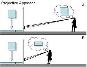
Figure 7. Projective approach. (A) Observer’s Distance = Artist’s Distance, Perceived Relative Depth is “square”. (B) Observer’s Distance < Artist’s Distance, Perceived Relative Depth is “compressed”.
(2) Compensation approach: vision uses perspective geometry and the “Artist’s Distance”, that is, the distance of the correct vantage point (see Figure 8). That is, to solve the inverse projection problem vision uses perspective geometry, and then corrects the perception to account for the difference between the “Observer’s Distance” (where the observer is when they look at the picture) and the Artist’s Distance. This, in theory, would cause the picture to look realistic from any position, and would be a possible explanation of perspective robustness. However, the Compensation approach cannot account for marginal or central distortions.
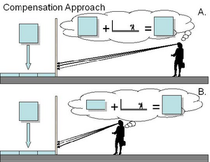
Figure 8. Compensation approach. (A) Observer’s Distance = Artist’s Distance, Perceived Relative Depth is “square”. (B) Observer’s Distance < Artist’s Distance, Perceived Relative Depth is “square”.
(3) Compromise approach: vision uses perspective geometry and the flatness of the picture plane (see Figure 9). That is, when vision solves the inverse projection problem, it also incorporates the flatness of the picture plane. This causes the perception of the entire scene to be flattened by a certain degree. The compromise approach can account for the compression observed in central distortions. It cannot, however, account for the elongation seen with marginal distortions, or for perspective robustness.
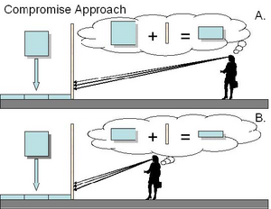
Figure 9. Compromise approach. (A) Observer’s Distance = Artist’s Distance, Perceived Relative Depth is “compressed”. (B) Observer’s Distance < Artist’s Distance, Perceived Relative Depth is “very compressed”.
(4) Invariant approach: vision uses perspective invariants (see Figure 10). An invariant is a relation that is constant over some transformation. In the case of a perspective picture, there exist relations that are invariant over changes in the observer’s position (i.e., they are invariant over transformation of Observer’s Distance). Theoretically, such relations could be the basis for perspective robustness. The Invariant approach, however, cannot account for the distortions present in some perspective pictures (both marginal and central).
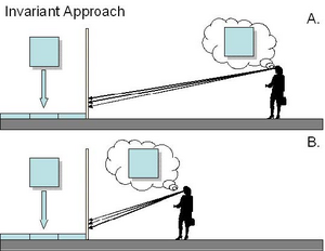
Figure 10. Invariant approach. (A) Observer’s Distance = Artist’s Distance, Perceived Relative Depth is “square”. (B) Observer’s Distance < Artist’s Distance, Perceived Relative Depth is “square”.
The Two Factors – Visual Angle Ratio and Angle from Normal
The theory that vision relies heavily on visual angle ratio and angle from normal, while simple, is very powerful. The two factors arise more widely than in viewing pictures. They are core terms for a general theory of perception. First, they allow us to express the visual system’s approximate-perspective function, the function that describes spatial perception. Secondly, they account for both perspective robustness and perspective distortions. Helpfully, they also predict perceived depth according to variables that can easily be measured objectively. Angle from normal can be measured as the angle between the direction from a given vantage point to a point on the object, and the direction given by parallel receding sides of the object. Visual angle ratio is measured for the sides of the objects at the same, given vantage point.
Technical Notes
#1 – Brunelleschi’s demonstration and proof
Brunelleschi devised a method for creating perspective pictures and calculating the proper amount of convergence for edges at 45º to the picture surface, as would be found in a picture of an octagonal building, such as the Baptistry in Florence (Tyler and Kubovy, 2004; Veltman, 1998). It is said that to show the picture was indeed recreating the same pattern of light as the real-world scene provided by Florence’s Baptistry, Brunelleschi conducted the following demonstration (see Figure 11).
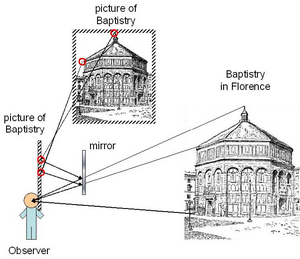
Figure 11. Schematic illustration of Brunelleschi’s demonstration. Notice that the light reflected from the picture (dashed lines) perfectly aligns with the light coming from the Baptistry in Florence (solid lines).
Brunelleschi took his picture of the Baptistry and drilled a small hole in it. He then stood directly in front of the Baptistry, turned his picture so that the painted side faced away from him, and looked through the small hole. In this way, Brunelleschi could see the real Baptistry building, but not the painted side of his painting.
To complete the demonstration, Brunelleschi held up a mirror in front of his painted side of the picture. That is, this mirror faced Brunelleschi, and was between the Baptistry and the picture. The mirror blocked the view of the real Baptistry, but now reflected Brunelleschi’s painting of the Baptistry. In this way, the mirror reflected the pattern of light produced by the painting. By moving the mirror in and out, Brunelleschi could test if his painting of the Baptistry recreated the same pattern of light as the real Baptistry. The two patterns of light were identical to observers, demonstrating that the perspective method that Brunelleschi developed truly did reproduce the pattern of light in a picture that was present in the real world scene.
The mathematical proof he is thought to have devised shows that a Baptistry side at 45º to the picture surface should be drawn converging to a point on the pictured horizon at a certain distance to one side of the center of the picture. Consider the observer’s vantage point (see Figure 12). Drop a perpendicular to the picture surface, to a point on the picture called the “foot of the normal”. Let the distance from the vantage point to the foot of the normal be x. The distance from the foot of the normal to the point on the pictured horizon to which the sides at 45º converge is y. Brunelleschi is thought to have proved that x = y. The reason is the side of the Baptistry at 45º is parallel to any line from the vantage point at 45º to the picture surface. A line at 45º to the picture surface from the vantage point must hit the painted horizon line at a point with distance x from the foot of the normal, by isosceles triangles (the angle at the foot of the normal is 90º, and the line is 45º to the picture surface).
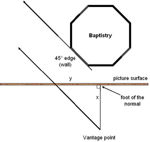
Figure 12. Overhead view of the octagonal Baptistry in Florence. Note that parallel edges of all surfaces that are at 45º to the picture surface will be drawn with lines converging to a point that is a distance y from the foot of the normal.
#2 – Extent of foreshortening and forelengthening
Consider a scene that is to be depicted on a picture surface. Relative to the picture surface, the scene has width (the dimension parallel to the picture surface) and depth (the dimension perpendicular to the picture surface). In a perspective picture, the projection of the depth dimensions causes “foreshortening”. That is, edges that recede in depth are depicted by lines that are drawn shorter on the picture surface than lines depicting edges in width. This, however, is not the general case, there can also be “forelengthening”, where edges in depth are drawn with lines that are longer than edges in width.
When does foreshortening versus forelengthening occur? Consider a square tile on a ground plane (see Figure 13). Foreshortening occurs when the angle between the normal to the picture plane and the deepest edge of the tile (α) is less than 45º. Forelengthening occurs when the angle between the normal to the picture plane and the deepest edge of the tile (α) is greater than 45º. At 45º, depth is neither foreshortened nor forelengthened, but depicted to a line equal in length to the line depicting width.
Proof: when α = 45º, depth is neither foreshortened or forelengthened. In other words, x = y (see Figure 13).
By similar triangles:
(1) x/s = c1/(c1+c2).
By similar triangles:
(2) y/p = c1/(c1+c2).
Therefore, by (1) and (2):
(3) y/p = x/s.
If x = y, then by (3):
(4) p = s.
By isosceles triangles:
(5) ξ = β = 45º.
By parallel lines and (5):
(6) β = θ = 45º.
By triangle theorem:
(7) θ + α + 90º = 180º.
Therefore:
(8) θ + α = 90º.
And by (6) and (8):
(9) α = 45º.
The proofs that foreshortening occurs when α < 45º, and forelengthening occurs when α > 45º are similar.
#3 – Rate of change in visual angle ratio
Consider an object laying on the ground in front of you, for example, one of the tiles in Figure 5. This tile has a certain visual angle ratio. As the distance between you and the tile increases, this visual angle ratio decreases. In particular, the visual angle ratio approaches 0 as the distance approaches infinity. This is because of the different rates of change for the visual angle of the width (see Figure 14A) and the visual angle of the depth (length) of the tile (see Figure 14B). The visual angle of the width decreases at a slower rate (rate is linear with distance) than the visual angle of the depth (rate is squared with distance).
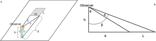
Figure 14. Consider a rectangular tile lying on the ground, with an observer with height h at a distance of d from the tile. (A) Overhead view of the rectangular tile. The visual angle of the width (W) is ξ. (B) Side view of the rectangular tile. The visual angle of the length (L) is α.
Proof: Visual angle of an object’s width is inversely proportional to the distance of the object (see Figure 14A).
(1) tanξ = W/v. By Pythagorean theorem (see Figure 14B) and (1)
(2) tanξ = W/√(d2+h2) For large distances (d), ξ is small. For small angles, tanξ≈ξ, so
(3) ξ≈ W/√(d2+h2). Therefore, ξ is proportional to 1/√d2, in other words
(4) ξ ~ 1/√d2. So,
(5) ξ ~ 1/d.
Proof: Visual angle of an object’s length (depth) is inversely proportional to the squared-distance of the object (see Figure 14B).
(1) α = β – θ.
(2) tanβ = (d+L)/h.
(3) tanθ = d/h.
By the tangent subtraction rule and (1),
(4) tanα = tan(β-θ) = (tanβ – tanθ)/(1 + tanβtanθ).
By (2), (3), and (4),
(5) tanα = [(d+L)/h – d/h]/[1 + (d+L)/h x d/h].
Simplifying (5), we get,
(6) tanα = L/(h + d2 – dW).
For large distances (d), α is small. For small angles, tanα≈α, so
(3) α≈ L/(h + d2 – dW).
Therefore,
(4) α ~ 1/d2.
Bibliography
- della Francesca, P. (1981). De prospectiva pingendi [Of the perspective of painting]. In E. G. Holt’s (Ed.), A documentary history of art (Vol. 1, pp. 256-267). New Jersey: Princeton University Press. (Original work published 1480).
- Juricevic, I., & Kennedy, J. M. (2005a, July). Perspective picture perception and the ART theory. Paper presented at the biannual International Conference on Perception and Action (ICPA), Monterey, CA.
- Juricevic, I., & Kennedy, J. M. (2005b, July). Object constancy: Object orientation affects relative depth in perspective pictures? Poster presented at the biannual International Conference on Perception and Action (ICPA), Monterey, CA.
- Juricevic, I., & Kennedy, J. M. (2005c, July). Perspective picture perception: a test of the ART theory. Poster presented at the biannual International Conference on Perception and Action (ICPA), Monterey, CA.
- Niall, K.K. (1992). Projective invariance and the kinetic depth effect. Acta Psychologica, 81, 127-168.
- Niall, K.K., & Macnamara, J. (1989). Projective invariance and visual shape constancy. Acta Psychologica, 72, 65-79.
- Niall, K.K., & Macnamara, J. (1990). Projective invariance and picture perception. Perception, 19, 637-660.
- Norman, J.F., Todd, J.T., Perotti, V.J., & Tittle, J.S. (1996). The visual perception of three-dimensional length. Journal of Experimental Psychology: Human Perception and Performance, 22, 173-186.
- Tyler, C. & Kubovy, M. (2004). The Rise of Renaissance Perspective. In Science and art of perspective. Available: http://webexhibits.org/sciartperspective/index.html Veltman, K. H. (1998). Definitions and Origins. In The sources and literature of perspective, volume I. Available: http://www.sumscorp.com/perspective/Vol1/title.html Wagner, M. (1985). The metric of visual space. Perception & Psychophysics, 38 (6), 483-495.